LM393 comparator chip, mainly in the following aspects:
One. What kind of chip is LM393?
Two. The function of each pin of LM393.
Three. Working principle of LM393 comparator.
Four. LM393 comparator parameters.
Five. LM393 voltage comparator circuit diagram.
Six. LM393 IC equivalent IC.
Seven. The purpose of LM393.
One. What kind of chip is LM393?
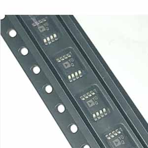
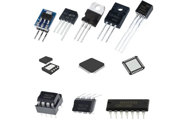
The LM393 is a widely used voltage comparator IC available in 8-pin Dip, SO-8 and other packages. The LM393 contains two independent high-precision comparator operational amplifiers that can be powered from a single or dual supply.
The wide supply voltage range allows it to be used in a variety of applications. The chip requires low operating current, which is very suitable for portable and battery-powered equipment, and the output drive logic system can be used in digital circuits. The LM393 has a maximum output current of 20mA, enough to drive transistors and logic systems.
Two. The function of each pin of LM393
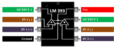
LM393 pin diagram
Pin 1: Output 1, the output pin of the operational amplifier 1
Pin 2: Inverting Input 1, the inverting input pin of op amp 1
Pin 3: Non-inverting input 1, non-inverting input pin of op amp 1
Pin 4: GND, Ground This is the IC's ground pin and needs to be connected to the negative (-) terminal of the supply voltage
Pin 5: Inverting input 2, non-inverting input pin of op amp 2
Pin 6: Non-inverting input 2, inverting input pin of op amp 2
Pin 7: Output 2, this is the output pin of op amp 2
Pin 8: Virtual Control Center This is the positive pin of the IC and needs to be connected to the positive (+) terminal of the supply voltage
Three. Working principle of LM393 comparator
The application of the LM393 is very similar to the LM311 comparator IC, only the specifications are a bit different. LM311 is often used to replace LM393. Like all voltage comparators, the LM393 has an inverting pin and a non-inverting pin. If the voltage at the non-inverting terminal (pin 2) is higher than the inverting terminal (pin 2), the output (pin 7) will also be high, otherwise the output will be low.
Now assume the LM393 is powered from the +5V supply voltage circuit. In this type, VCC+ (pin 8) is connected to the +5V supply voltage and VCC (pin 4) is grounded to keep it at 0V potential. An example circuit is shown below where the inverting terminal is set to 2.5V and the non-inverting terminal voltage is varied using a potentiometer.
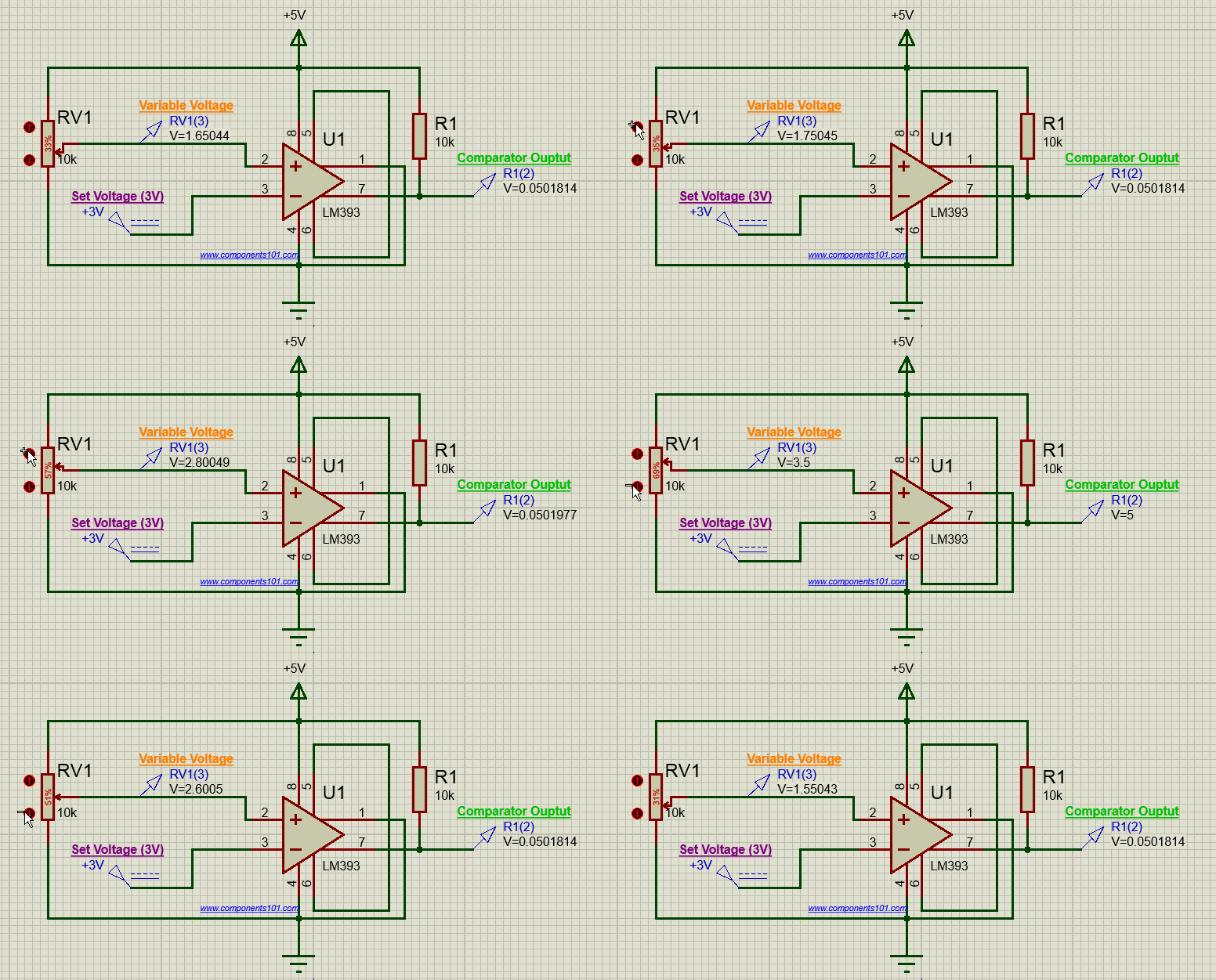
When the voltage of pin 2 is higher than that of pin 7, the output voltage remains high and vice versa. If you want to manually adjust the DC offset voltage, pins 5 and 6 on the op amp are used to set the balance voltage. These pins are generally not used because the input offset itself is better controlled. When not in use, pins 5 and 6 should be shorted as shown above. You can also see that the collector pin (pin 7) of the transistor is used for output and the emitter pin (pin 1) is grounded, this design is called "collector output circuit".
Four. LM393 comparator parameters
Single Supply Voltage – 2V to 36V,
Differential i/p voltage – 36V,
Packages – DIP and SOIC 8-pin,
Drain Current - 0.4mA,
Storage Temperature – -65°C/W to 150°C/W,
Lead temperature – 260°C,
Power consumption – 660mW,
Split Supplies – ±1V to ±18V, and Input Offset Voltage.
Low Input Bias Current of 25nA
Low Input Offset Current of 5nA
Differential input and supply voltage ranges are equivalent
Output Voltages Ideal for ECL, MOS, DTL, TTL and CMOS Logic Levels
Electrostatic discharge bolts on the input increase the roughness of the device without compromising its performance
Five, LM393 voltage comparator circuit diagram
1. List of components
LM393 integrated circuit
Photoresistor/Photosensor
33KΩ resistor
330Ω resistance
Potentiometer (range from 1KΩ – 20KΩ)
load
3 "AA" batteries or DC power supply
2. Comparator night light circuit based on LM393 IC
The circuit uses a photoresistor to control the voltage divider circuit. When this circuit absorbs bright light, the output device will be turned off. When the circuit absorbs darkness, the output device will be turned off. The circuit works on the principle of a voltage comparator. If the inverting terminal of the IC voltage is higher than the non-inverting terminal, the output device activates. Likewise, if the voltage at the inverting terminal of the IC is lower than the non-inverting terminal, the output device is disabled. Here, the circuit uses LEDs as output devices.
The IC has two power inputs, namely Vcc and GND, where Vcc is the positive voltage power supply up to 36V, and GND is the ground of the voltage source. Power channels can be done with these two terminals and provide power for this operation.
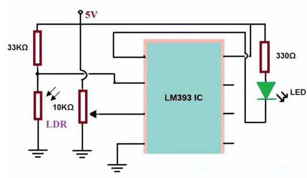
Comparator night light circuit based on LM393 IC
3. Working principle
After the IC is powered on, compare the voltage values. If the voltage at the inverting terminal is higher than the voltage at the non-inverting terminal, the op amp output will be grounded and current will flow from the positive supply to GND. Likewise, if the voltage at the inverting terminal is lower than the non-inverting terminal, the op amp output will remain at the positive supply voltage (Vcc) and no current will flow because there is no potential difference across the load.
Therefore, when the voltage at the inverting terminal is high, the load will be turned on. When the inverting terminal voltage is low, the load will be turned off. Here LED is used as load. The night light circuit using LM393 is shown in the figure above. The circuit uses an LED as a load and a photoresistor to detect light. The resistance of a photoresistor depends primarily on the light that hits its surface. When the photoresistor detects darkness, the resistance of the photoresistor becomes high, and when the photoresistor detects bright light, its resistance decreases.
So if we connect a voltage divider circuit using a photoresistor and a fixed resistor, if it detects darkness, the photoresistor will utilize more voltage because it has less resistance in darkness. Similarly, a photoresistor will use less voltage if it detects bright light.
If the input of the non-inverting terminal of the op amp is a relatively stable reference voltage, the voltage of the photoresistor is higher than the reference voltage in the dark, and lower than the reference voltage in the light. A comparator is designed here. When there is night and then there is light, the function of the circuit different. Therefore, the LED will light up in the dark and turn off in bright light.
Six. LM393 IC Equivalent IC
LM358, TL082, LM311, LM193, LM293, LM2903
Seven. Application of LM393
Voltage Comparator Circuit
It can be used to drive relays, lights, motors, etc.
Zero crossing detector
Battery powered applications
High Voltage Protection/Warning
Oscillator circuit
Peak Voltage Detector
Delay generator
If you have any demand, please feel free to contact us through BOM, we are the most professional inventory supply company.

