One. Regulator
A fixed or linear voltage regulator is a device or circuit responsible for providing a constant DC output voltage for any variation in input voltage or load conditions. It is the most important part of electronic equipment. It acts as a buffer to protect the components of the circuit from damage. It can regulate AC and DC voltages according to its design.
There are two main types of voltage regulators. One is a linear regulator; the other is a switching regulator. Both types of regulators regulate the voltage of the system, but linear regulators work less efficiently than switching regulators. We will discuss linear regulators in detail.
linear regulator
A linear voltage regulator is a voltage regulator device used to keep a specified output voltage constant as the input voltage and load conditions vary. It uses an active pass device (such as a BJT or MOSFET) controlled by a high-gain amplifier. The variable conductivity of the active transfer element is responsible for maintaining the output voltage. The performance of a linear regulator is to act as a voltage divider to produce a regulated output voltage.
In a linear regulator, a linear element such as a resistive load is used to regulate the output voltage. A transistor stays in its active or ohmic or linear region of operation during voltage regulation.
In order to maintain a constant output voltage, the internal resistance can be varied. The variable resistance is provided by using a transistor controlled by the feedback loop of the amplifier.
Linear regulators are also known as buck converters, where the output voltage is always less than the input voltage. It takes some power and turns it into heat to produce a constant output voltage.
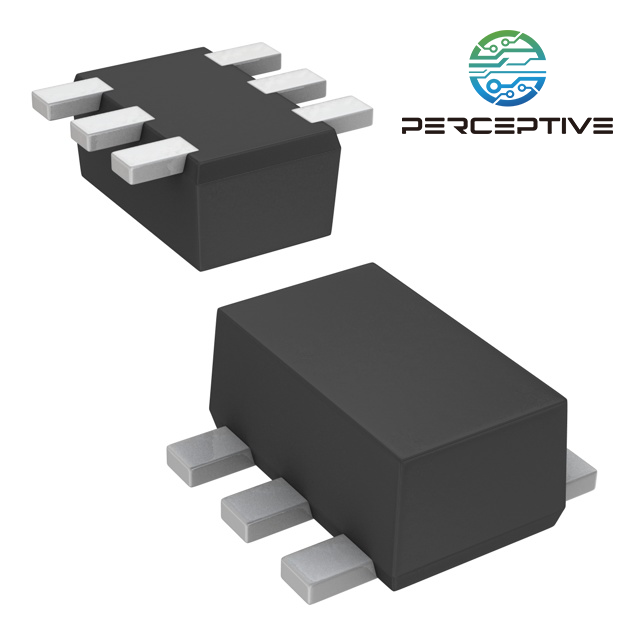
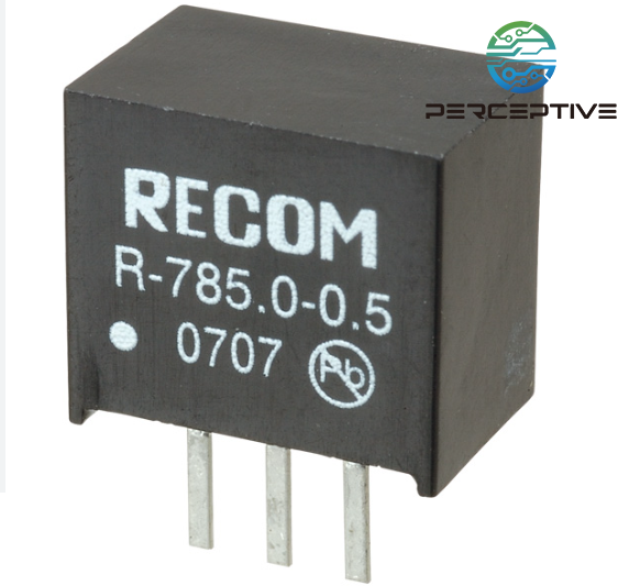
A linear regulator typically consists of three pins: an input pin, an output pin, and a ground pin. The pin diagram of the LM7805 regulator is shown in the figure.
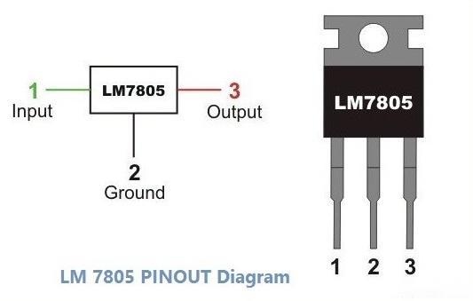
Two. Types of Linear Regulators
There are mainly two types of linear regulators depending on the connection to the load.
1. Series Regulator
In a series regulator, a variable element or active transfer element such as a transistor is connected in series with the connected load. A constant output voltage across the load is achieved by varying the resistance of the series elements with respect to the load.
The series regulator is the more common form of regulator. It is more efficient than a shunt regulator.

The circuit diagram of a typical series regulator
In this circuit, the output voltage is measured with a voltage divider between R_1 and R_2. This voltage is compared with the reference voltage V_REF. The resulting error signal controls the conduction of pass elements such as transistors. Therefore, the voltage across the transistor changes, so the output voltage across the load remains constant.
A Zener diode regulator is a type of series regulator. It minimizes the ripple of the supply voltage and improves regulation. This type of regulator is less efficient due to the non-zero zener resistance and can be improved by limiting the zener current.
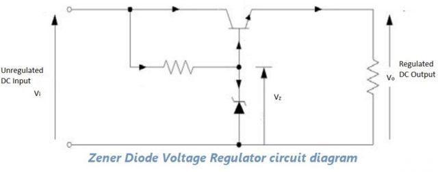
The circuit diagram of Zener diode regulator
The main advantage of a series regulator is that the load efficiently uses the amount of current drawn. Even if the load doesn't need any current, it doesn't draw all of it. Therefore, series regulators are much more efficient than shunt regulators.
Series regulators are relatively inefficient compared to switching regulators. But it has the advantage of being simple, and there are no switching spikes on their outputs.
2. Shunt Regulator
In a shunt regulator, a regulating element or an active transfer element such as a transistor is connected in parallel with the connected load. Further, the voltage limiting resistor is connected in series with the load. To maintain a constant output voltage across the load, the level of current must be drawn through a series resistor.
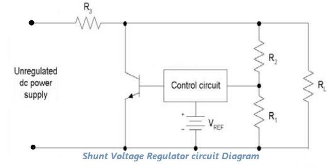
The circuit diagram of a typical shunt regulator
In this circuit, the conduction of the transistor is controlled based on the feedback and the reference voltage. The circuit is designed in such a way that the current through the series resistor remains constant. As the current through the transistor changes, the output voltage across the load remains constant.
Shunt regulators are slightly less efficient than series regulators, but are simpler to implement. Shunt regulators are used in very low power circuits where very little current is wasted. This type of regulator is common in voltage reference circuits.
Three. Advantages of Linear Regulators:
Very simple to implement and easy to use
Provides low output ripple voltage
Has a fast loading response time
Low noise, low electromagnetic interference
More cost-effective
Four. Disadvantages of linear regulators:
The efficiency is relatively low.
The output voltage is always less than the input voltage, i.e. it only performs a step-down operation.
A heatsink is required as it dissipates excess power as heat and gets very hot during conditioning.
Need a lot of space.
Five. Application
Linear regulators have many applications. One of the most common examples is mobile chargers. The adapter provides the AC signal. However, the output voltage signal is a regulated DC signal. Every power supply uses a voltage regulator to provide the required output voltage. Computers, TVs, laptops, and all manner of devices are powered using this concept.
Small electronic circuits run on voltage regulators. Even the slightest voltage signal fluctuation can damage circuit components such as ICs. When it comes to power generation systems, voltage regulators play a vital role in their operation. Solar power plants generate electricity based on the intensity of sunlight. It needs a voltage regulator to ensure a steady stable output signal.
Similar Model

